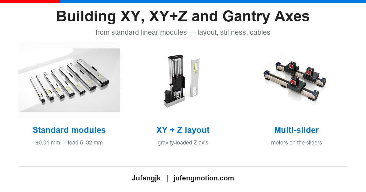
Building XY, XY+Z and Gantry Axes from Standard Linear Modules
One linear module is a component. Three of them are a machine — and a machine brings problems a component does not: errors that stack, a structure that deflects, and a load path that decides which axis wears out first.
This guide covers the three layouts we are asked about most often, the numbers that decide between them, and the integration details that are usually discovered too late.
Why three modules are not a three-axis machine
Bolting three accurate modules together does not give you an accurate machine, for three reasons that have nothing to do with the modules themselves.
The load path. In any stacked arrangement, the bottom axis carries everything above it — the upper axis, its motor, the payload, and an overhung moment that grows with the offset between the two carriages. The bottom axis is always the most heavily loaded part of the machine.
The structure between them. Every joint, plate and bracket between two modules is a place where squareness and stiffness are lost. Two modules at ±0.01 mm on a base that is not flat will not produce a ±0.01 mm machine.
Gravity, once an axis points up. A vertical axis carries its load permanently, which is a different sizing problem from a horizontal one.
The three layouts, and what each is good at
| Layout | How it is built | Best when | What to watch |
|---|---|---|---|
| Stacked XY | One axis rides on the carriage of the other | Compact envelope, modest work area, lowest cost | The lower axis carries the upper axis plus an overhung moment; deflection grows with the cantilever |
| Gantry | Two parallel rails carry a bridge; the cross axis travels on the bridge | Wide work area, heavy or long workpieces, spans one module cannot cover | The two rails must be level, parallel and square to each other; the bridge itself deflects under load |
| XY + Z | A vertical axis mounted on a stacked XY or on a gantry bridge | Pick and place, dispensing, inspection — anything the tool has to reach down to | The Z axis is gravity-loaded; holding torque and a fail-safe brake decide whether it drops on power loss |
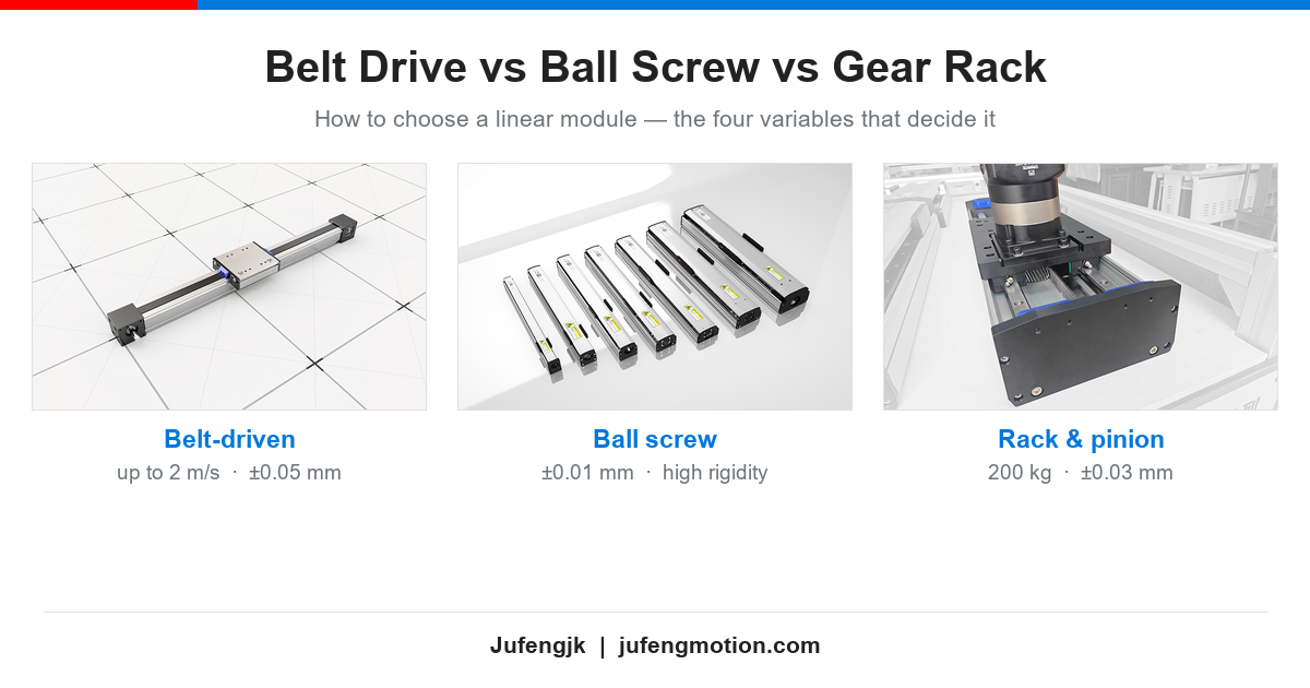
For long spans and heavy bridges, a rack and pinion axis is usually the answer rather than a longer screw: our rack modules reach a repeat positioning accuracy of ±0.03 mm over strokes beyond 10,000 mm, with horizontal loads up to 200 kg, and are built for gantry systems. For the horizontal axes themselves, the drive choice is a separate decision — see our comparison of belt, ball screw and rack and pinion.
Five numbers that decide the layout
Before drawing anything, put these on one page. Most layout arguments end once they are written down.
1. Payload and overhung moment, per axis
Not the payload alone — the moment. A 10 kg tool hanging 300 mm out from the carriage loads the guides very differently from the same 10 kg sitting directly above them. Work out the moment for the top axis first, because it propagates downward.
2. Stroke per axis
Stroke decides whether a module is enough or whether the axis needs a gantry. It also decides how the drive behaves: a long screw loses critical speed, while a belt or a rack covers the span without that limit.
3. Cycle time
The axis with the longest travel usually sets the cycle, not the fastest axis. It is common to spend money on a fast Z axis while the long X axis remains the bottleneck.
4. The accuracy you actually need at the tool
Two axes at ±0.01 mm do not give you a ±0.02 mm machine — and they do not give you ±0.01 mm either. Whatever the module datasheets say, the result is set by the structure between them. Specify the tool-level requirement, then work backwards with margin.
5. Duty cycle
A machine that indexes once a minute and one that runs continuously at 1 m/s are different machines even with the same strokes. Duty cycle decides the drive, the guide preload and how much of the accuracy budget you should spend on the structure.
Where multi-axis accuracy is actually lost
In practice the losses are rarely in the modules. They are in these four places:
The base. Flatness and parallelism under the rails set the straightness of every axis above them. Machined, stress-relieved and checked — not just welded and painted.
Squareness between axes. An X and a Y that are 0.1 mm out of square over 500 mm will make every rectangular part a parallelogram, no matter how good the modules are.
Deflection at the tool. A cantilever in a stacked XY and a bridge in a gantry deflect in different directions. Check the deflection at the tool, not at the carriage.
Thermal drift. A screw that runs warm grows; a two-metre frame moves more than a small one. On long machines this is a real budget item, not a footnote.
Cable management, which is decided last and should not be
The axes are the visible part of the design; the cables are what stop the machine from reaching its rated life.
Use continuous-flex cable in the chain. Standard cable work-hardens and breaks inside a moving chain — usually at the copper, months after commissioning.
Allow for the stroke. Cable length has to cover the full travel plus the chain's bend radius; a chain sized to the drawing, not to the stroke, is a common late surprise.
Put connectors on the fixed end. Motor and encoder connectors on the moving carriage become a fatigue point and a service problem.
What we supply for multi-axis builds

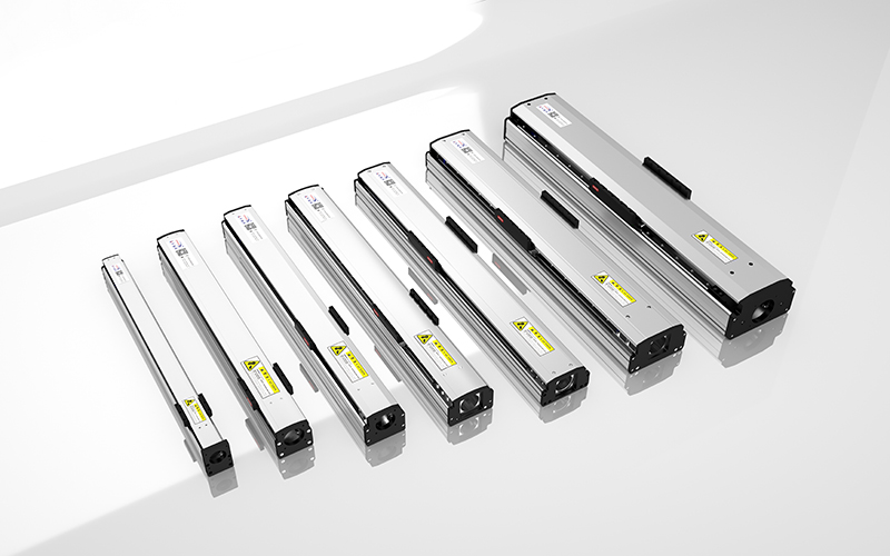
Our JFJK-S ball screw linear modules are the usual building block for the positioning axes: ±0.01 mm repeatability, lead options from 5 mm to 32 mm, and customisable stroke, with the motor interface integrated into the module housing rather than added as a separate bracket.
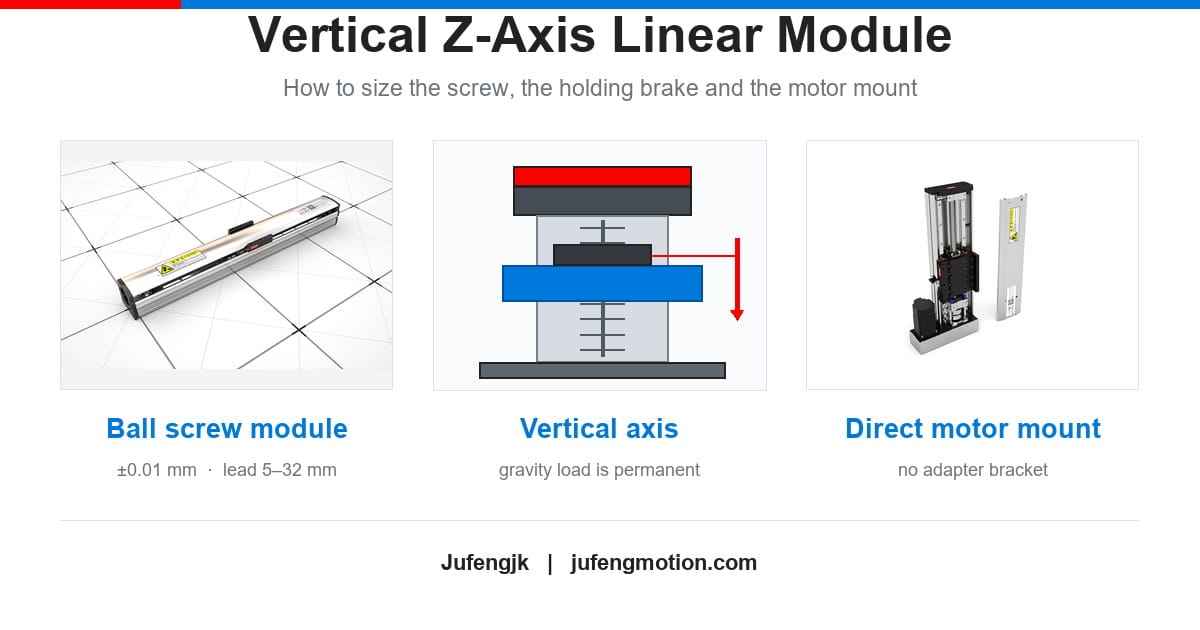
For the vertical axis, the module can be supplied in five motor mounting arrangements — direct connection, folded under, in front, above or behind — so the drive can be placed to suit the machine envelope. The sizing rules for that axis are in our vertical Z-axis guide.

Where the layout needs several heads on one axis, our multi-slider and motor-on-slider modules put more than one carriage, or the motor itself, on the same profile. Multi-axis XY and XYZ gantry configurations are available as complete assemblies, and long-span gantry axes are normally built on our rack and pinion modules.
Three mistakes we see on multi-axis builds
Designing the stack top-down. The lightest axis belongs on top. Building upward and choosing the bottom axis last usually means the bottom axis is undersized for the moment it carries.
Trusting the modules to fix the base. Two accurate modules on an un-machined frame give an inaccurate machine, and the modules get blamed for it.
Treating the Z axis like a horizontal one. It is the only axis on the machine with a permanent load, and the only one that can drop a load when the power goes off.
FAQ
Can I build a gantry from two standard modules?
Yes, and it is the common route. The modules are the straightforward part; the work is in getting the two rails level, parallel and square, and in the stiffness of the bridge between them.
Do I need a special controller?
For coordinated motion, yes — the controller has to interpolate the axes. Independent point-to-point moves can be done with separate drives, but any path that has to stay straight needs interpolation.
How do I keep accuracy across three axes?
Start at the base. Squareness and flatness are cheaper to fix in the frame than to compensate for in the control, and they do not drift with temperature the way a software correction can.
Summary
Choose the layout from the load path and the work area, not from the module catalogue. Check the moment on every axis, decide stroke and cycle time together, and expect the accuracy to be set by the base and the joints rather than by the modules. Then size the vertical axis for gravity, and give the cables the same attention as the mechanics — those are the three things that decide whether the machine still holds its accuracy a year after commissioning.
Send us your stroke, payload, cycle time and the layout you have in mind, and we will size the axes together.