Vertical Z-Axis Linear Module: How to Size the Screw, Servo and Brake
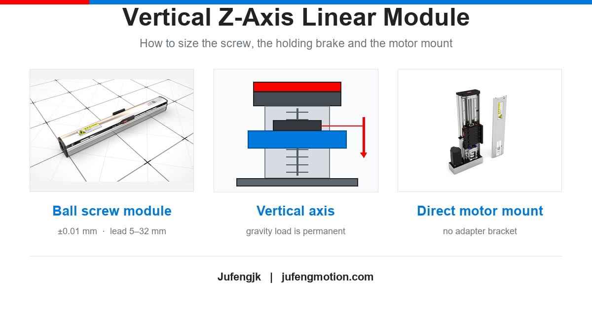
A horizontal axis only has to move its load. A vertical axis has to hold it — at every standstill, and again after the power is switched off. That single difference changes the screw lead you should pick, the torque you have to check, and the safety device you must fit.
This guide covers what actually changes when the axis points up.
Why a vertical axis is a different problem
On a horizontal axis, gravity acts perpendicular to travel. It appears in the calculation as guide friction (F = μ · m · g) and nothing else.
On a vertical axis, gravity acts along the direction of travel. The axis carries a permanent axial load — while accelerating, while moving at constant speed, while sitting still, and after the drive has been disabled.
Two consequences follow:
-
The motor must produce torque simply to hold position. Holding torque is continuous torque, so it heats the motor through I²R losses. A vertical axis is continuous duty even when it looks idle.
-
If the load can rotate the screw, the carriage will fall the moment the drive is switched off.
That is why a Z axis is not an X axis rotated 90°.
Ball screws are efficient — and that is the problem
Screw drives are generally preferred over belts and linear motors on vertical axes, because a screw resists a catastrophic free fall. But resistance is not safety: a vertical load can still back-drive a screw, overcoming the screw's inefficiency, the system friction and the lead angle.
The difference between screw types comes down to efficiency:
-
Lead screws have low efficiency, which is normally a drawback — but on a vertical axis it works in your favour. A lead screw rarely back-drives, and the smaller the lead, the less likely it is.
-
Ball screws are the opposite. Their high efficiency (typically around 90 %) is exactly why they are accurate and long-lived, and exactly why they are more likely to let the load fall.
A useful rule of thumb: to prevent back-driving, keep the lead below one third of the screw diameter. Check that against your catalogue — for precision ball screws, that is rarely where a designer ends up.
You can also check it quantitatively. Back-drive torque is a function of the axial load, the lead and the reverse efficiency (0.8 to 0.9 for ball screws). If that torque is smaller than the total friction in the assembly — the drag torque of the ball nut, the seals and the end bearings — the load is unlikely to move the screw. In a published example, a 16 × 10 ball screw carrying 100 N produced a back-drive torque of 0.13 Nm against 0.26 Nm of system friction, so back-driving was unlikely.
But "unlikely" is not a safety device. The calculation tells you which fail-safe mechanism you need — a supplementary brake, or a counterweight — it does not replace one.
The five things to size, in order
1. The axial load — including gravity, in both directions
Start from the force the screw actually sees:
Fa = m · g + F (process) + μ · m · g
On a vertical axis the gravity term never disappears — not even when the axis moves down. While descending, gravity assists the motion, so the required motor torque can fall close to zero or turn negative, and the drive then has to control the descent rather than drive it. A Z axis that is stable going up can still run away on the way down.
2. The lead — a trade that gets worse when the axis points up
Lead is the travel per screw revolution. A longer lead gives more speed at the same motor RPM, but it also demands more torque for the same load and reduces positioning resolution.
On a vertical axis there is a third penalty: back-drive torque rises with the lead. A lead that is ideal for a fast horizontal axis can make the same axis difficult to hold once it points up. When in doubt on a Z axis, go one step shorter on lead than you would horizontally, and re-check the speed requirement.
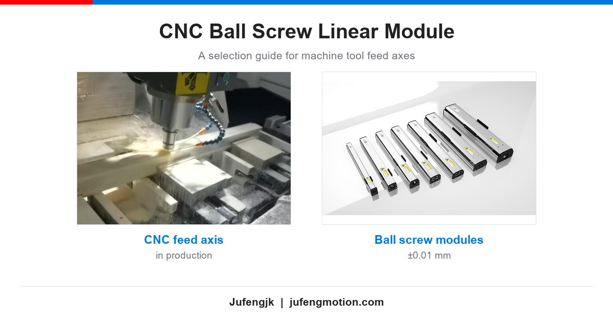
Our ball screw linear modules are available with lead options from 5 mm to 32 mm, so most speed and resolution combinations are covered — but the vertical case is the one where that choice has to be made deliberately. For the general screw selection checklist — accuracy grades, sealing and duty cycle — see our CNC ball screw linear module selection guide.
3. Screw diameter and stroke — buckling and critical speed
Two limits get worse as stroke grows, and both are more severe on a vertical axis:
-
Critical speed. A screw starts to vibrate laterally above a certain RPM, and that limit falls as the free length increases. A 1000 mm screw can spin far faster than a 3000 mm one.
-
Buckling. A vertical screw in compression behaves like a column. If the compressive load exceeds the critical buckling load, the screw bends. Euler's relation makes this sensitive to both span and diameter: the critical load rises roughly with the fourth power of the diameter and falls with the square of the length.
Buckling is the failure mode that is distinctly worse vertically, because the compressive load is permanent. If the stroke is long and the load heavy, the options are a larger screw diameter, a tension mounting arrangement, or a different drive type altogether.
4. Holding torque and the brake
Size the motor on continuous torque, not peak. A vertical axis may hold position for most of its cycle, and holding current is what heats it.
Then decide what happens when the power goes away. The standard answer is a spring-applied, electrically released brake on the motor: it is fail-safe, because the spring engages the brake when the coil is de-energised, and the drive releases it during normal operation.
Two rules worth repeating:
-
A motor holding brake is a holding device. It is designed to hold a static load, not to stop a moving one. Decelerating a load on the brake wears the friction surfaces and can quietly reduce its torque. Stop the axis with the drive, then let the brake hold.
-
If you rely on the servo to hold the carriage by current alone, the axis is only as safe as its power supply and its tuning. On a power loss the drive disables, and the load is unopposed.
5. Motor, coupling and the motor interface
The module carries its own motor interface. Our ball screw modules are supplied with an integrated motor mount, so the motor flange attaches to the module housing itself — there is no separate adapter bracket in the drive train.
On a vertical axis that matters, because every extra interface is another place for misalignment to enter the drive train. With an integrated mount, the joint you have to get right is the coupling or the pulley, not an adapter plate.
Direct connection is not the only arrangement we build. Five motor mounting positions are available, so the drive can be placed to suit the machine envelope instead of the other way round:
-
Direct connection — the motor sits on the end of the module, in line with the screw.
-
Folded under — the motor is turned back underneath the module.
-
Folded in front — the motor is folded towards the front face of the axis.
-
Folded above — the motor is folded over the top of the module.
-
Folded behind — the motor is folded to the rear of the module.
A folded arrangement shortens the axis, which is often what decides whether a Z axis fits inside an existing machine.
-
Tell us the motor model and flange when you order. Mounting configurations are customisable, so the motor interface is made to suit the motor you are actually using.
-
Use a flexible coupling to absorb small angular and radial misalignment. A rigid coupling needs near-perfect alignment.
-
Allow for length. Adding a brake makes the motor longer — confirm the envelope before the drawing is frozen. On a Z axis this is one of the most common late surprises.
Brake, counterweight, or a different drive?
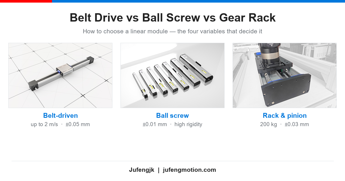
If you have not yet fixed the drive type, start from our comparison of belt, ball screw and rack and pinion. Once the drive is a screw and the axis is vertical, the holding strategy is the next decision.
| Approach | What it does | Best when | Watch out for |
|---|---|---|---|
| Spring-applied brake on the motor | Holds the load when power is removed; fail-safe by design | Almost every vertical ball screw axis | Holding only — not for dynamic stops; adds motor length; needs a release circuit |
| Counterweight or air balance | Takes gravity out of the motor's continuous duty; improves vertical dynamics | Heavy carriages, high duty cycle, high acceleration | Extra mass and space; adds inertia; needs its own guiding |
| Short lead (below one third of screw diameter) | Passive resistance to back-driving | Light loads, low speed | Rarely sufficient on its own for a precision ball screw; limits speed |
| Belt drive | Lowest cost for very long vertical strokes | Very long stroke, moderate precision | A belt does not hold a vertical load — the axis drops unless a brake is fitted; belt stretch |
| Lead screw | Naturally resists back-driving | Low duty, low precision positioning | Low efficiency, wear, lower speed |
Five mistakes we see on vertical axes
-
Sizing the motor on peak torque. A vertical axis is continuous duty; check the continuous rating against the gravity load.
-
Ordering a brake-less servo and holding position with current. It works until the power fails.
-
Using the brake to stop a moving axis. It holds; it does not brake.
-
Ignoring buckling on long strokes. Vertically, the compressive load never goes away.
-
A motor flange that does not match the module interface. Forcing the fit tilts the motor, the coupling takes up the error, and the axis loses the accuracy the screw was bought for.
What we supply for vertical axes
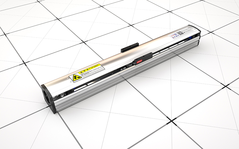
Our JFJK-S ball screw linear actuators are built for axes that point up as well as sideways: ±0.01 mm repeatability, lead options from 5 to 32 mm, high rigidity, and customisable stroke and mounting. Motor support is integrated, and multi-axis XY / XYZ gantry configurations are available for machines that need more than one precision axis.
Send us the moving mass, the stroke, the required speed and whether the axis is vertical — we will size the screw, the motor and the brake together.
FAQ
Can a ball screw hold a vertical load without a brake?
That is the worst assumption to build on. Ball screws are efficient by design and can be back-driven by a vertical load. Whether a specific assembly will back-drive can be checked by comparing the back-drive torque with the total friction in the screw assembly — but a calculation that says "unlikely" is not a safety device. For heavy or personnel-adjacent loads, fit a fail-safe brake or a counterweight.
Should I use a counterweight instead of a brake?
They solve different problems. A counterweight removes gravity from the motor's continuous duty and improves vertical dynamics. It is not a fail-safe holding device. Heavy, high-duty Z axes often use both.
My Z axis creeps slowly when it should be holding. Why?
Check three things in order: whether the brake is engaged when the drive is disabled, whether the motor's continuous torque covers the static load with margin, and whether the position loop is tuned for a gravity-loaded axis. Creep is almost always one of those three.
Can I use a belt-driven module on a vertical axis?
For very long strokes it can be the economical option, and a belt covers strokes a screw cannot. But the belt will not hold the carriage — a motor brake is mandatory, and belt stretch has to be allowed for in the positioning budget.
Summary
A vertical axis is sized around gravity, not around speed. Include the gravity term in the axial load, choose the lead knowing that back-drive torque grows with it, watch buckling on long strokes, size the motor on continuous torque, and fit a fail-safe holding device instead of trusting a calculation. Get those five right and the axis behaves. Get one wrong and the symptom usually shows up as creep, drift, or a dropped load.
Not sure which way your Z axis should go? Send us the axis data and we will size it with you.