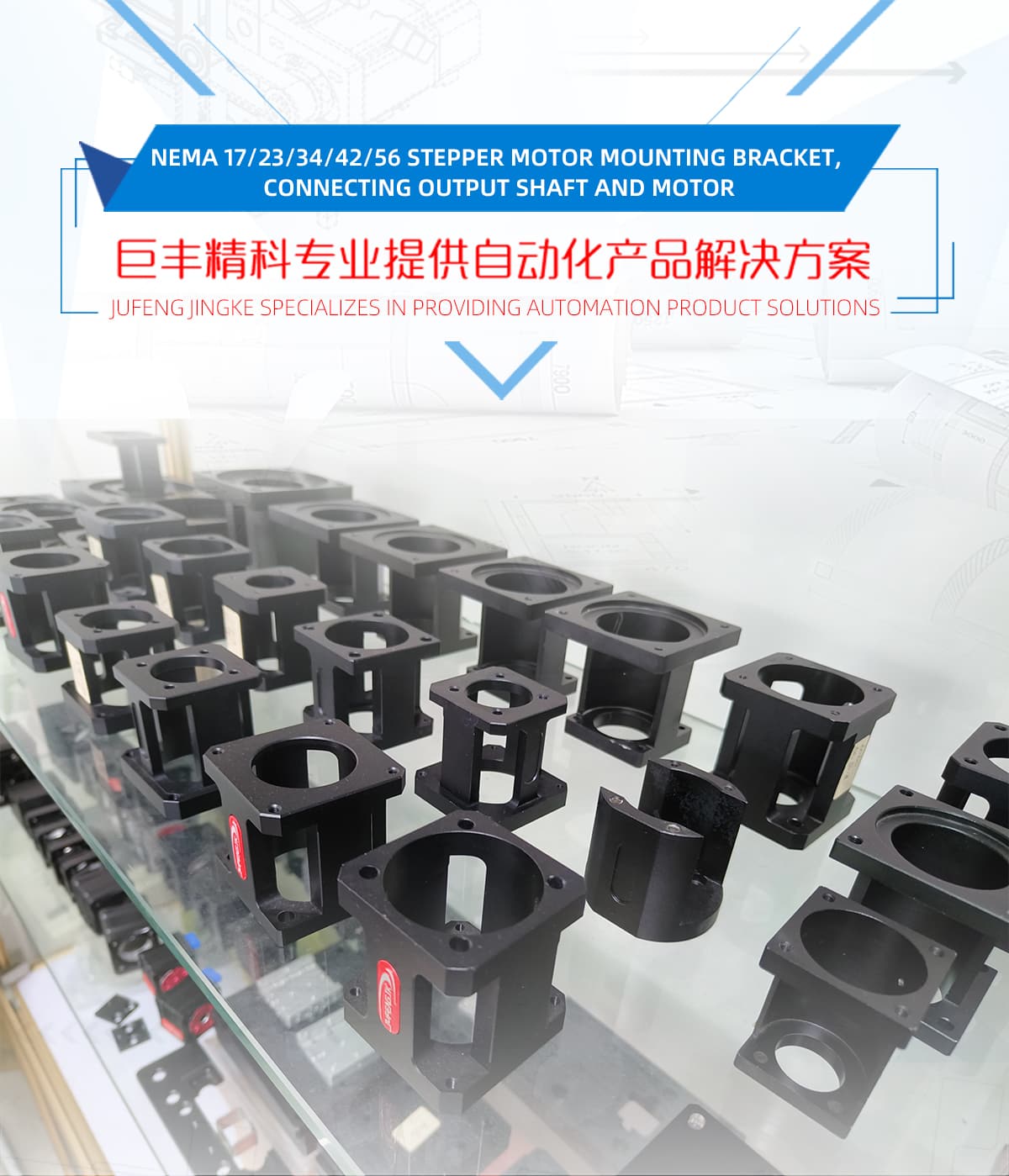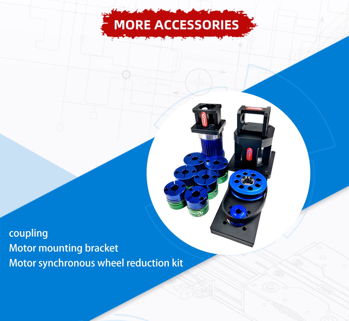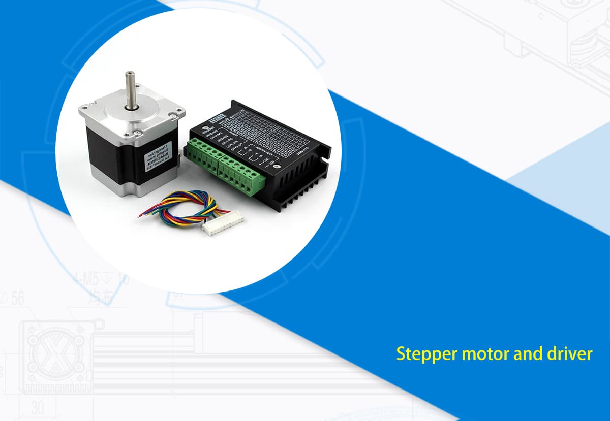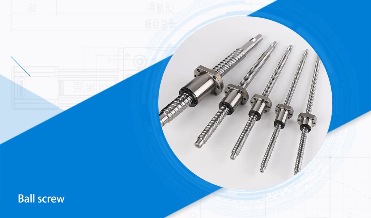
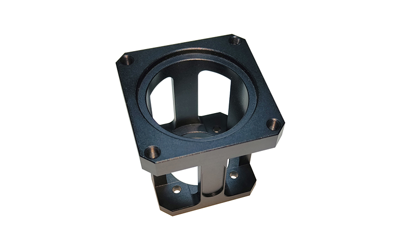
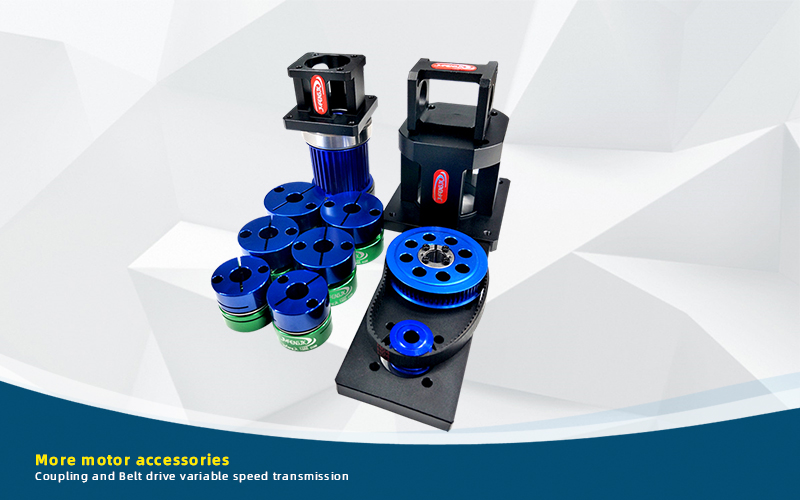
Stepper Motor Mounting Brackets (NEMA 17 to NEMA 56)
NEMA Standard Sizes
Robust Construction
Quick Mounting
Vibration Dampening
Cost-Effective
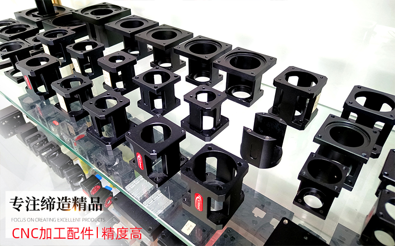
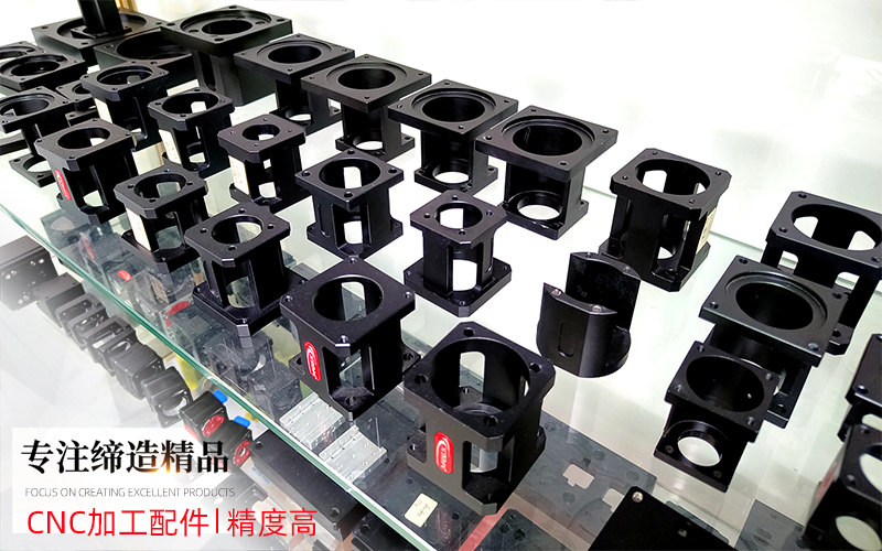
A stepper motor has no encoder, so nothing corrects a flange that is out by a tenth. Whatever the flange does to the motor axis stays in the motion, as lost steps at one end of travel or as a periodic mark on the surface a belt-driven stage produces. We machine these bodies from 6061 aluminium on our own CNC machining centre in Shenzhen, in the same shop that builds the modules they bolt onto, and most of them share one feature that servo flanges usually do not: a slotted boss for belt tension.
Why a stepper flange is a tensioning part, not just an adapter
NEMA fixes the bolt circle. It does not fix the pilot boss. Two NEMA 23 motors from different suppliers can arrive with different spigot diameters, or with no spigot at all, because the standard governs mounting holes and shaft height rather than the register that centres the motor. That is why every bracket here starts from a drawing around a motor frame instead of from a NEMA table.
The second difference is what the bracket has to do downstream. A stepper is normally paired with a timing belt, either as a reduction stage or as the drive itself, and a belt has to be tensioned in situ. Six of the eight drawings on this page carry a slotted boss with a 1 mm deep relief for exactly that reason. The slot is not a machining leftover. It is the adjustment travel, and it is the first thing to check when a belt stage keeps walking or squealing after assembly.
A third point matters more on steppers than on servos. Steppers run open loop and are usually driven at a high step rate near their torque limit, so a bracket that flexes under torque reversal does not just lose position once. It loses it every cycle, in the same direction, until the part being made is visibly stepped.
Eight drawings across three frame sizes
The table is taken from our own drawing set. Frame sizes are the measured body square, with the NEMA designation that corresponds to it.
| Drawing no. | Frame | Body | Spigot | Fixing holes | Length | Weight |
|---|---|---|---|---|---|---|
| WDT3030-01-12 | 42 mm (NEMA 17) | 42 x 42 mm | Ø22 +0.06/+0.03 | 4 x Ø3.5 + 4 x Ø4.5 | 50 mm | 0.06 kg |
| WDT4040-01-14 | 42 mm (NEMA 17) | 42 x 42 mm | Ø22 +0.06/+0.03 | 4 x Ø3.5 + 4 x Ø4.5 | 50 mm | 0.07 kg |
| WDT3030-01-15 | PX42 gearbox | 42 x 42 mm | Ø25 +0.06/+0.03 | 4 x Ø4.5 on Ø38 PCD | 50 mm | 0.06 kg |
| WDT3030-01-14 | 57 mm (NEMA 23) | 56.5 x 56.5 mm | Ø38.1 +0.06/+0.03 | 4 x M4 through | 45 mm | 0.073 kg |
| WDT4040-01-13 | 57 mm (NEMA 23) | 57 x 57 mm | Ø38.1 +0.06/+0.03 | 4 x M4 through | 42 mm | 0.10 kg |
| WDT5050A-01-30 | 57 mm (NEMA 23) | 57 x 57 mm | Ø38.1 | 4 x M4 through, 4 x Ø5.5 | 60 mm | 0.15 kg |
| WDT5050-01-17A | Universal seat | 62 x 55 mm | Ø54 +0.03/0 | 4 x M5 x 10 deep + 4 x Ø5.5 on Ø72 PCD | 57 mm | 0.17 kg |
| WDT5050A-01-33 | 86 mm frame | 86 x 86 mm | Ø80 +0.06/+0.02 | 4 x M6 on Ø100 PCD + 4 x Ø5.5, Ø10 c-bore | 16 mm | 0.18 kg |
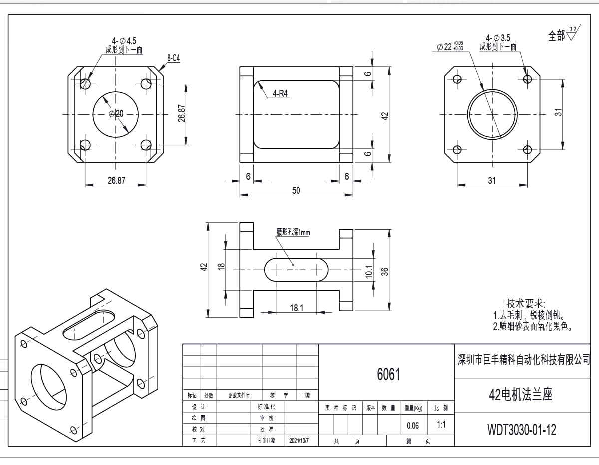
WDT3030-01-12, the 42 mm bracket: 50 mm overall length on a 36 mm base, 22 mm spigot on a 20 mm bore, and the slotted boss that gives the belt its adjustment.
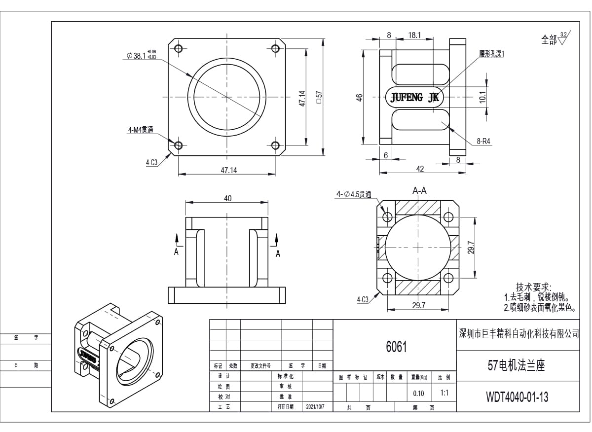
WDT4040-01-13, the 57 mm bracket: 42 mm long, 38.1 mm spigot held to a 0.03 mm band, four M4 through holes on the standard 47.14 mm square.
Three things are worth reading from that table. The 42 mm and 57 mm bodies both exist in more than one length, because the distance from the motor face to the first pulley or coupling varies with the motor stack, not with the frame size. The spigot tolerances are all two-sided bands that start above nominal, so the bracket assembles by hand and still holds centre. And the fixing holes are through holes on M4 or M5 rather than tapped holes, which is what you want on a cast or extruded motor end bell.
The 42 mm family: three parts that look alike
All three 42 mm brackets share the same 50 mm overall length, the same 42 mm height and the same 22 mm spigot. They differ in the base and in what bolts onto the far side.
| Drawing no. | Receives | Base width | Slot centre | Bore | Weight |
|---|---|---|---|---|---|
| WDT3030-01-12 | NEMA 17 motor | 36 mm | 18 mm | Ø20 | 0.06 kg |
| WDT4040-01-14 | NEMA 17 motor | 40 mm | 22 mm | Ø20 | 0.07 kg |
| WDT3030-01-15 | PX42 planetary gearbox | 36 mm | 18 mm | Ø20 | 0.06 kg |
The two motor brackets differ only in base width, 36 mm against 40 mm, with the slot position following it. Choose the wider base when the belt run needs the slot further out from the motor centreline; the narrower one fits where the mounting surface is already constrained. Everything else, including the 18.1 mm slot and the 10.1 mm slot width, is identical, so the two are interchangeable on the motor side.
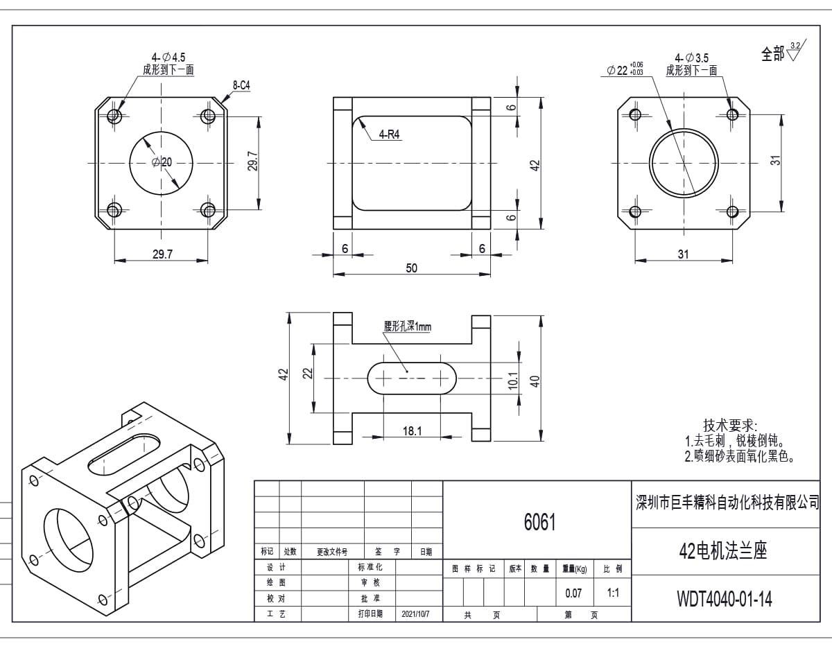
WDT4040-01-14: the wider 42 mm base at 40 mm, slot centre at 22 mm. Spigot and bore are unchanged from the narrower version.
The 57 mm family follows the same logic over a larger range. WDT4040-01-13 is the short 42 mm body for a compact stack. WDT3030-01-14 sits at 45 mm with a 22 mm through bore and a 12 mm internal cavity, which is the version to use when the coupling has to sit inside the bracket. WDT5050A-01-30 goes to 60 mm and adds a 48 mm register on the output side for a pulley block or a second bearing plate.
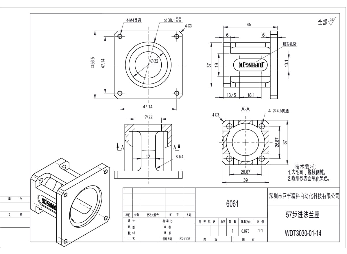
WDT3030-01-14: 45 mm long, 32 mm bore opening into a 12 mm cavity, 8 mm radii on the slot ends. The lightest 57 mm option at 0.073 kg.
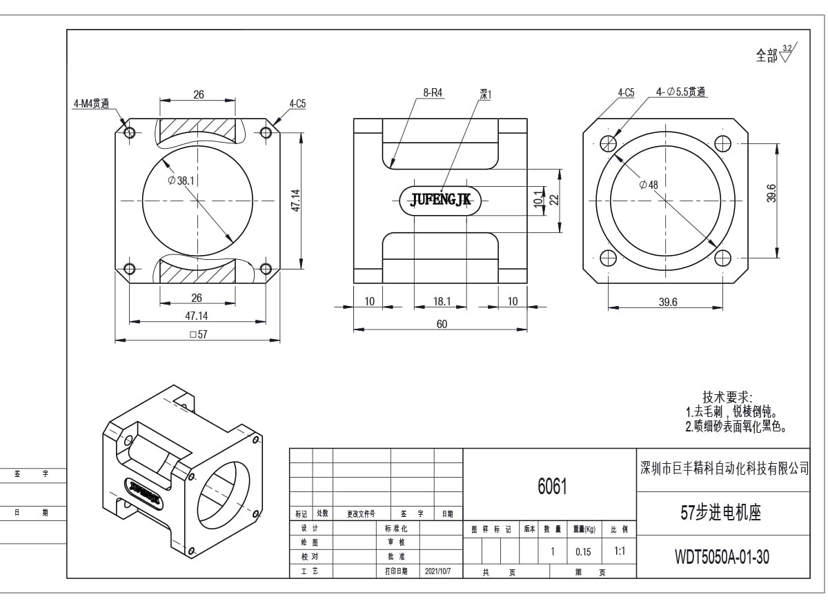
WDT5050A-01-30: the long 57 mm body at 60 mm, with a 48 mm register on the output side for a pulley block.
Gearbox flanges: PX42 and the 86 mm plate
A planetary reducer changes the flange problem. The motor still bolts to the input side, but the bracket now has to present a 25 mm register to the gearbox instead of a 22 mm register to a motor, and the gearbox flange pattern is set by the reducer maker rather than by NEMA. WDT3030-01-15 is drawn for the PX42 frame: 25 mm spigot held to +0.06/+0.03, four 4.5 mm holes on a 38 mm circle, 20 mm through bore, and the same slotted base as the motor version so the belt can still be tensioned after the reducer is fitted.
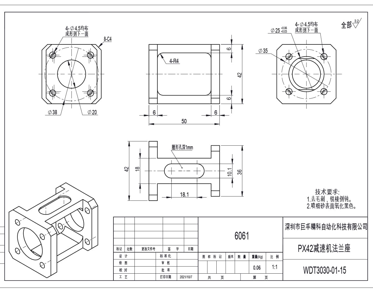
WDT3030-01-15, the PX42 gearbox flange: 38 mm bolt circle on the reducer side, 25 mm register, 20 mm through bore, slotted base retained.
The 86 mm plate is the other end of the range. WDT5050A-01-33 is 16 mm thick with an 80 mm register on a 0.04 mm band and four M6 holes on a 100 mm circle, plus four 5.5 mm holes with 10 mm counterbores for the mating plate. At this frame size the motor torque arrives as a bending load rather than a point load, so the plate is kept thick and the register is kept large rather than adding ribs.
Machined in-house: custom patterns for steppers
Custom is a specific offer here, not a slogan. Every bracket on this page is cut on machines we run, from the same 6061 stock we use for module end plates, so a change is a program edit rather than a purchase order to a subcontractor.
What we change most often on stepper brackets:
Slot length and position - the adjustment travel is the first thing a belt stage runs out of, and it is the cheapest thing to change before the first batch.
Body length - to suit a coupling or pulley that is deeper than the standard stack.
Spigot diameter - for motors whose pilot boss does not match the catalogue drawing, which happens more with steppers than with servo frames.
Output-side register - a second bearing plate or a pulley block often needs its own locating diameter, as on WDT5050A-01-30.
Gearbox side - reducer flange patterns differ between PX, PL and third-party planetary frames, and the drawing has to follow the reducer you actually bought.
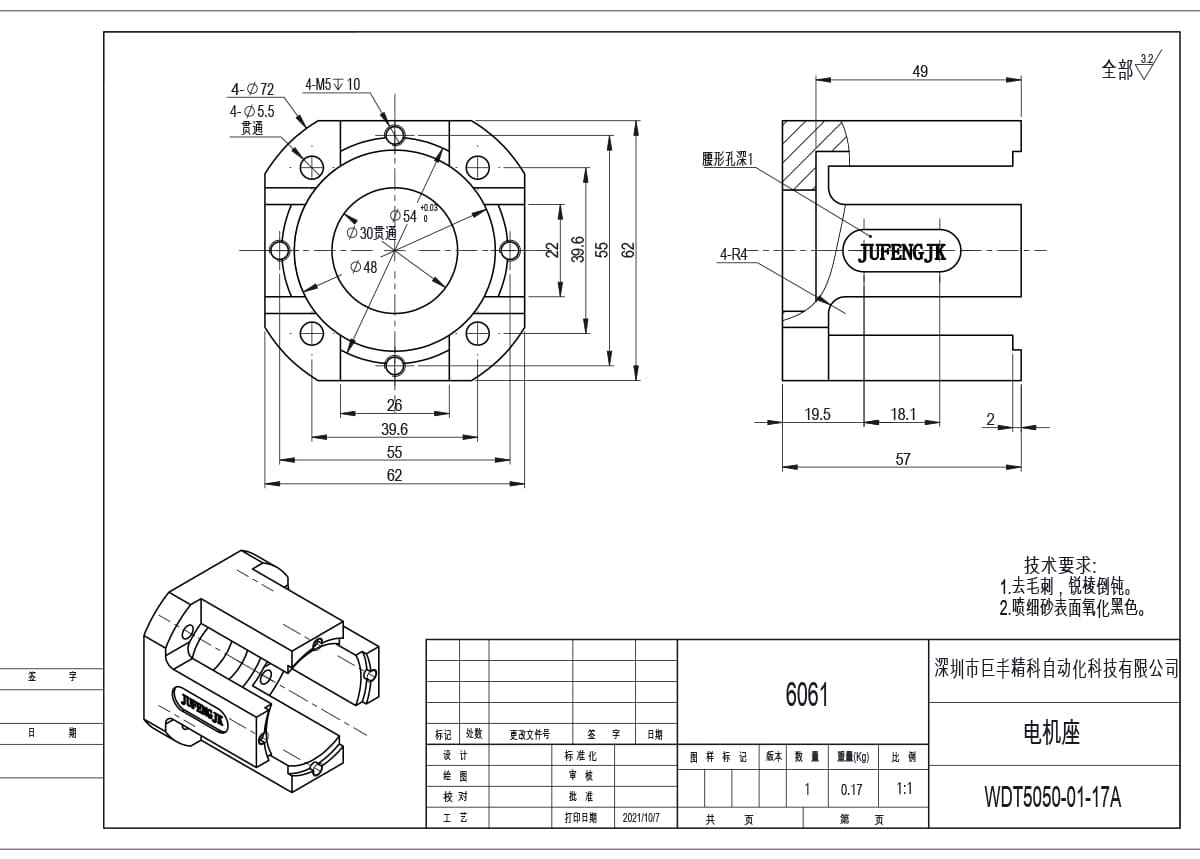
WDT5050-01-17A, the universal seat: 54 mm register, 30 mm through bore opening to 48 mm, two hole patterns on one body. This is the drawing most often re-cut for a customer frame.
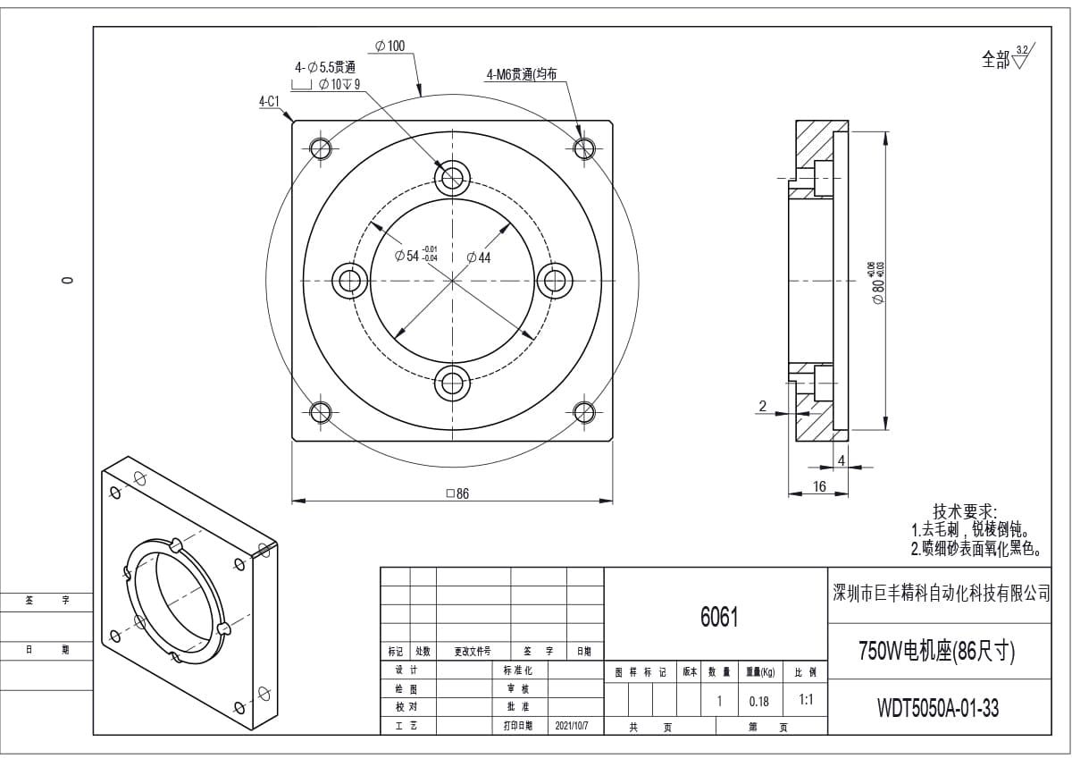
WDT5050A-01-33, the 86 mm plate: 16 mm thick, 80 mm register, four M6 on a 100 mm circle, counterbored for the mating plate.
OEM work runs the same way. Send a PDF, a STEP file or a dimensioned sketch of the motor face and the belt layout; we return a drawing number, the spigot tolerance we intend to hold, and a first-article part to check before a batch is released. Because the drawing, the program and the finished part stay in one building, a revision comes back as a revised part rather than as a new supplier to qualify.
Material, finish, and what to send with an enquiry
All eight drawings carry the same material callout and the same two process notes.
| Item | Standard | Option |
|---|---|---|
| Material | 6061 aluminium | C45 steel for structural brackets |
| Surface finish | Ra 3.2 all over | Ground spigot face on request |
| Treatment | Bead blast, then black anodising | Natural anodising or black oxide |
| Edge condition | Deburr, chamfer all sharp edges | As drawn fillets retained |
| Slot detail | 1 mm deep relief as drawn | Through slot on request |
A flange quote goes wrong when the motor is described loosely. Send these six things and we can answer with a drawing number instead of a question:
Motor make and model, or the frame drawing with the pilot boss diameter
Frame size, and whether a gearbox sits between motor and bracket
Slot requirement: length, position, or belt centre distance
Body length, or the coupling and pulley dimensions you are working with
Whether the output side needs its own register or bearing plate
Quantity per size, and whether you need a first-article sample
If the motor is a servo rather than a stepper, the same body sizes are drawn separately: see our servo motor mounting flanges from 100 W to 1.5 kW. For the belt stage itself, the matching synchronous pulleys and timing wheels are cut to the same register sizes, and if you are building the axis around a belt module rather than a screw, start from the belt-driven linear modules.
Send your motor frame details to [email protected] and we will come back with the matching drawing number, the slot arrangement we would cut, and the price at your quantity. OEM and custom patterns are welcome; a non-standard stepper bracket is a normal order here, not an exception.