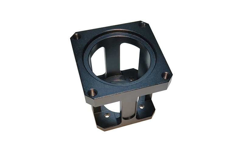
Servo Motor Mounting Brackets (100W to 1.5kW)
Precision Machined
High Rigidity
100W-1.5kW Compatibility
Easy Installation
Aluminum Alloy
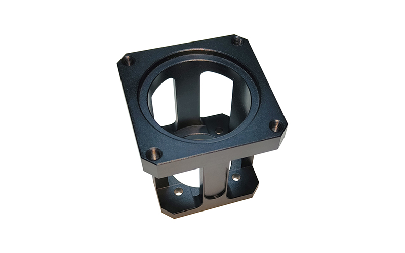
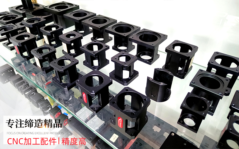
These flanges sit between a servo motor and a linear module, and the job they do is unglamorous and absolute: hold the motor square to the screw, keep the spigot concentric, and do not move when torque reverses. Every flange on this page is machined from 6061 aluminium on our own CNC machining centre in Shenzhen, in the same shop that builds the modules they bolt onto. Five sizes are drawn and held in stock, and any of them can be re-cut to a motor frame that no catalogue flange fits.
What a mounting flange actually controls
Three things, in this order of importance.
Concentricity. The spigot, the raised circular boss on the motor face, centres the motor shaft on the screw axis. The four fixing screws only clamp. Their clearance is far too large to locate anything, which is why a flange with an undersized or badly turned spigot produces a runout the coupling has to swallow. On a rigid coupling that runout goes straight into bearing load.
Squareness. The motor face and the mounting face have to be parallel. A motor sitting at an angle preloads the coupling in one direction and creates a once-per-revolution error that reads like screw backlash but is not. Replacing the screw will not fix it.
Stiffness. Under acceleration reversal the flange carries the full motor torque as a bending moment. A thin plate flexes, the motor nose moves, and repeatability drifts at the ends of travel even though the screw itself is fine.
Five standard sizes, with the drawing dimensions
The table below is taken directly from our drawing set, not from a catalogue summary. Every flange carries a drawing number you can match against your own assembly.
| Drawing no. | Motor | Body | Spigot | Fixing holes | Through bore | Weight |
|---|---|---|---|---|---|---|
| WDT4040-01-21 | 100 W servo | 42 x 42 mm | Ø30 +0.05/+0.02 | 4 x M4 on Ø46 PCD | Ø20 | 0.06 kg |
| WDT4040-01-24 | 400 W | 60 x 60 mm | Ø50 +0.06/+0.05 | 4 x M5 through, 49.5 sq. | Ø22 / Ø44 | 0.11 kg |
| WDT4545-01-18 | 400 W | 60 x 60 mm | Ø50 +0.06/+0.03, 3 mm deep | 4 x M5 through, 49.5 sq. | Ø22 / Ø44 | 0.16 kg |
| WDT5050-01-17A | Servo seat | 62 x 55 mm | Ø54 +0.03/0 | 4 x M5 x 10 deep + 4 x Ø5.5 on Ø72 PCD | Ø30 / Ø48 | 0.17 kg |
| WDT5050A-01-29 | 750 W | 80 x 80 mm | Ø70 +0.06/+0.02 | 4 x M5 through on Ø90 PCD | Ø44 | 0.13 kg |
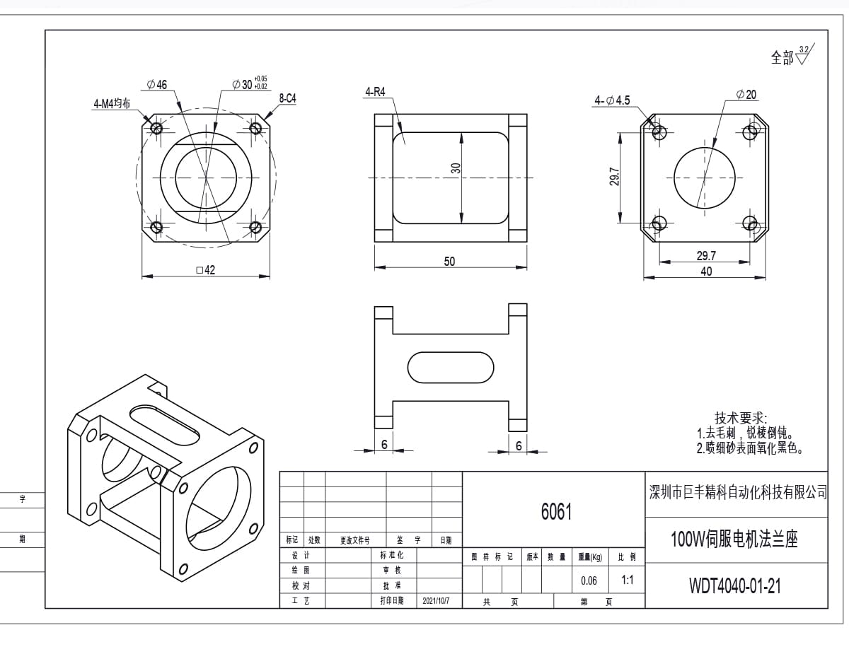
WDT4040-01-21, the 100 W flange: 42 mm square body, 30 mm spigot, four M4 holes on a 46 mm circle, 50 mm overall height.
The 100 W and two 400 W bodies are machined from bar stock in batches and held in stock. The 62 x 55 servo seat and the 750 W plate are cut to order, because at those sizes the motor frame varies more between brands than the NEMA table suggests.
If you are assembling a ball screw axis rather than a belt stage, the flange thickness sets how far the motor nose sits from the screw end, which in turn decides whether a standard coupling will fit. Our ball screw linear actuators are dimensioned with that stack height in mind.
Reading the spigot tolerance
The nominal spigot diameter is not the number that decides fit. The tolerance band is.
| Drawing no. | Spigot | Band width | What it gives you |
|---|---|---|---|
| WDT4040-01-21 | Ø30 +0.05/+0.02 | 0.03 mm | Motor spigot enters by hand, no rattle once seated |
| WDT4040-01-24 | Ø50 +0.06/+0.05 | 0.01 mm | Closest location fit in the range, assembly still tool-free |
| WDT4545-01-18 | Ø50 +0.06/+0.03, 3 mm deep | 0.03 mm | Recessed seat, protects the spigot edge during handling |
| WDT5050-01-17A | Ø54 +0.03/0 | 0.03 mm | Largest seat, used where the motor frame is the load path |
| WDT5050A-01-29 | Ø70 +0.06/+0.02 | 0.04 mm | Widest band, takes paint thickness and rework |
A 0.01 mm band is effectively a location fit: the motor spigot goes in with light hand pressure and cannot move once seated. A 0.03 to 0.04 mm band still holds the axis to a few hundredths and assembles without tools, which matters on a machine where the motor is already bolted into a frame. What you must avoid is a band that runs from nominal down to negative. That is an interference fit, and it will not go onto a motor you cannot press.
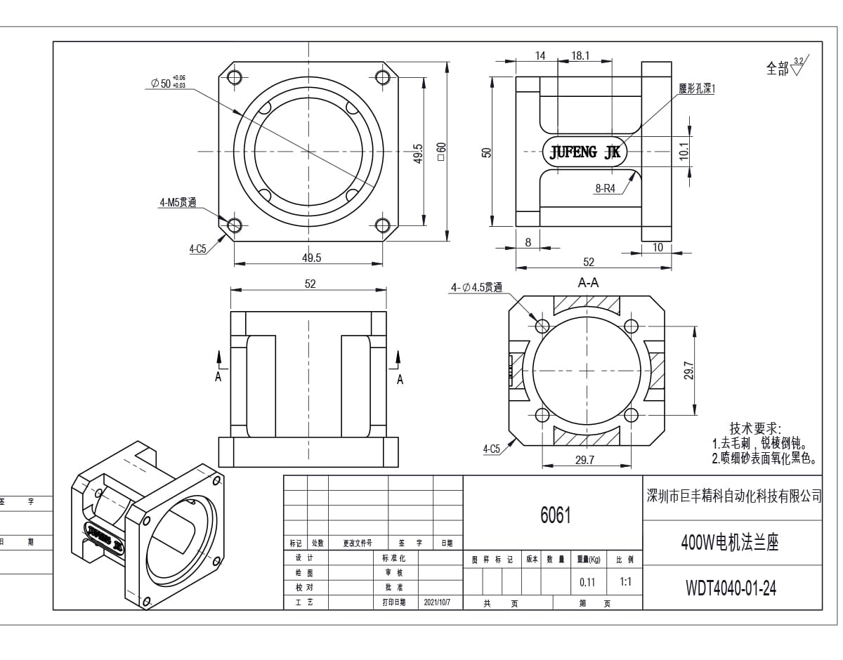
WDT4040-01-24, 400 W: 60 mm square, 50 mm spigot held to a 0.01 mm band, plus a slotted boss for belt tensioning.
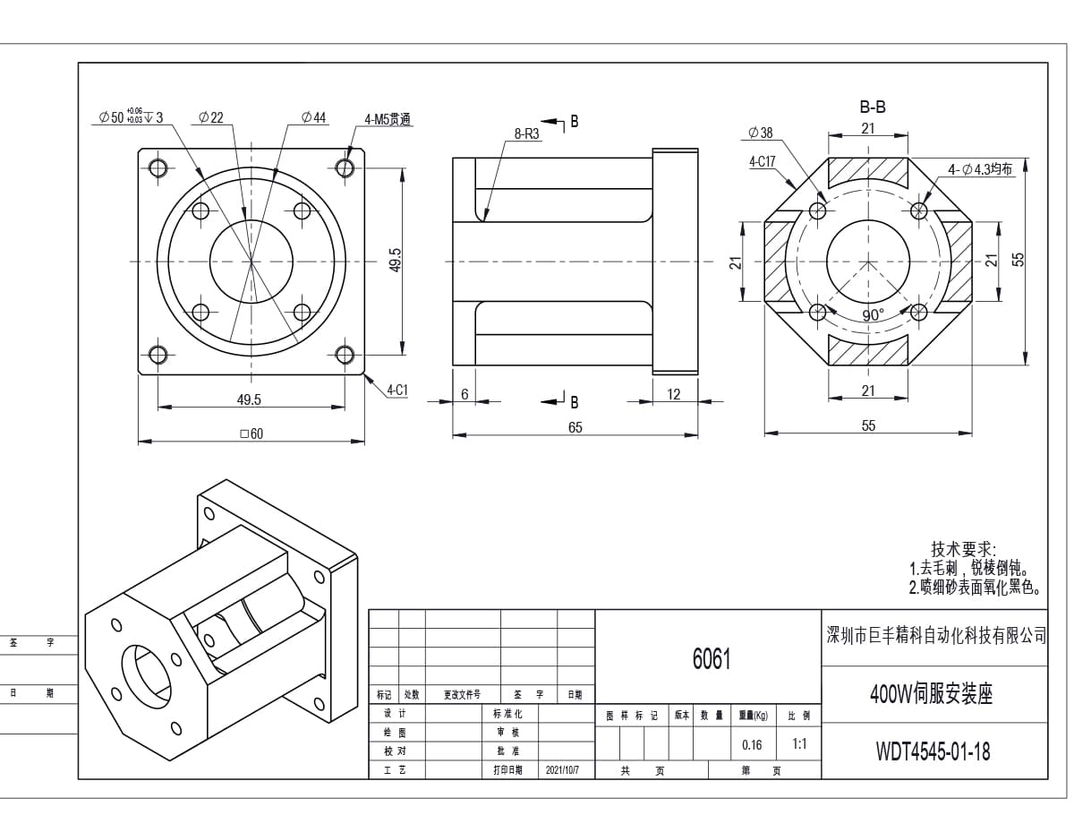
WDT4545-01-18, the 400 W mounting seat: same 60 mm bolt pattern but a 65 mm deep body that moves the motor clear of a pulley guard.
Machined in-house: stock sizes, or cut to your drawing
Custom is not a vague promise on this page. It means one of five specific changes, and every one of them is a program edit on a machine we run ourselves rather than a request sent out to a subcontractor.
What we change most often:
Hole pattern - pitch circle, thread size and clocking angle to suit a motor you already own, including frames that are not standard NEMA.
Spigot diameter - for motors with a pilot boss that no catalogue flange matches.
Body thickness - to clear a coupling guard or to shorten the stack between motor and screw.
Slots instead of round holes - for belt tensioning. Two of the standard drawings already carry a slotted boss for exactly this reason, and you can pair them with our synchronous pulleys and timing wheels.
Material - 6061 aluminium as standard, C45 steel where the flange also acts as a structural bracket.
OEM work runs the same way. Send a PDF, a STEP file or a dimensioned sketch of the motor face; we return a drawing number, the spigot tolerance we intend to hold, and a first-article part for you to check before a batch is released. Because the drawing, the program and the finished part stay in one building, a revision comes back as a revised part rather than as a new supplier to qualify.
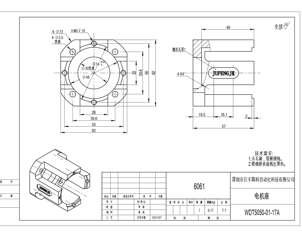
WDT5050-01-17A, the 62 x 55 motor seat: 54 mm spigot, 30 mm through bore, and a slotted boss for belt tension. This is the pattern most often re-cut for a customer frame.
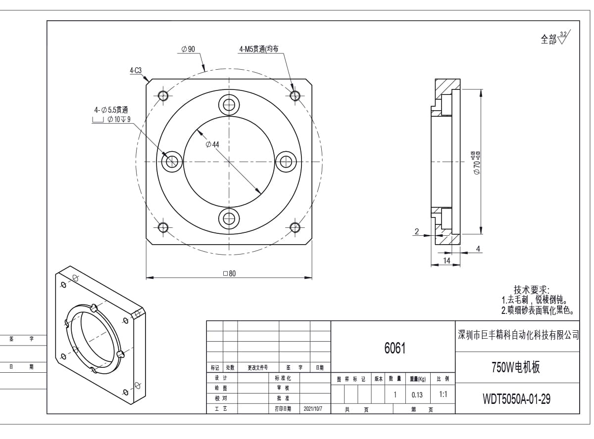
WDT5050A-01-29, the 750 W plate: 80 mm square, 70 mm spigot, 14 mm thick, four M5 holes on a 90 mm circle with 10 mm counterbores.
Material, finish and what the drawing notes say
All five drawings carry the same material callout and the same two process notes.
| Item | Standard | Option |
|---|---|---|
| Material | 6061 aluminium | C45 steel for structural brackets |
| Surface finish | Ra 3.2 all over | Ground spigot face on request |
| Treatment | Bead blast, then black anodising | Natural anodising or black oxide |
| Edge condition | Deburr, chamfer all sharp edges | As drawn fillets retained |
Ra 3.2 across the part is a general machined finish: fine enough for an anodised cosmetic surface and for the spigot to seat cleanly, without the cost of a ground face. Where a flange doubles as a datum, the spigot face can be ground instead, and that is worth asking for on any axis where you intend to hold repeatability below the screw grade.
What to send with an enquiry
A flange quote only goes wrong when the motor is described loosely. Send these six things and we can come back with a drawing number rather than a question:
Motor make and model, or the frame drawing with the pilot boss diameter
Motor rated power and frame size
Required spigot diameter and whether it must be recessed
Hole pattern, or the mating plate it has to bolt to
Overall thickness, or the coupling length you are working with
Quantity per size, and whether you need a first-article sample
For NEMA-frame stepper motors the pattern is fixed by the standard, so those are a stock item: see our stepper motor mounting brackets from NEMA 17 to NEMA 56. Servo frames are the opposite case, which is why every servo flange here starts from a drawing.
Send your motor frame details to [email protected] and we will come back with the matching drawing number, the spigot tolerance we would hold, and the price at your quantity. OEM and custom patterns are welcome; a non-standard flange is a normal order here, not an exception.
[object Object][object Object][object Object][object Object][object Object]